Subscribe to our newsletter here
Would you like to always be the first to know about our latest products and offers? Then we have good news for you! With our newsletter campaign we bring all important information directly to your inbox.
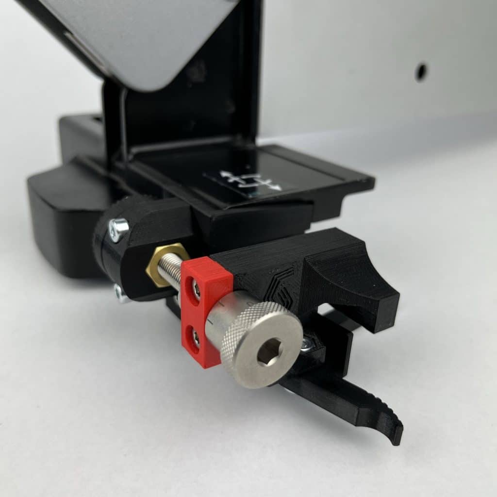
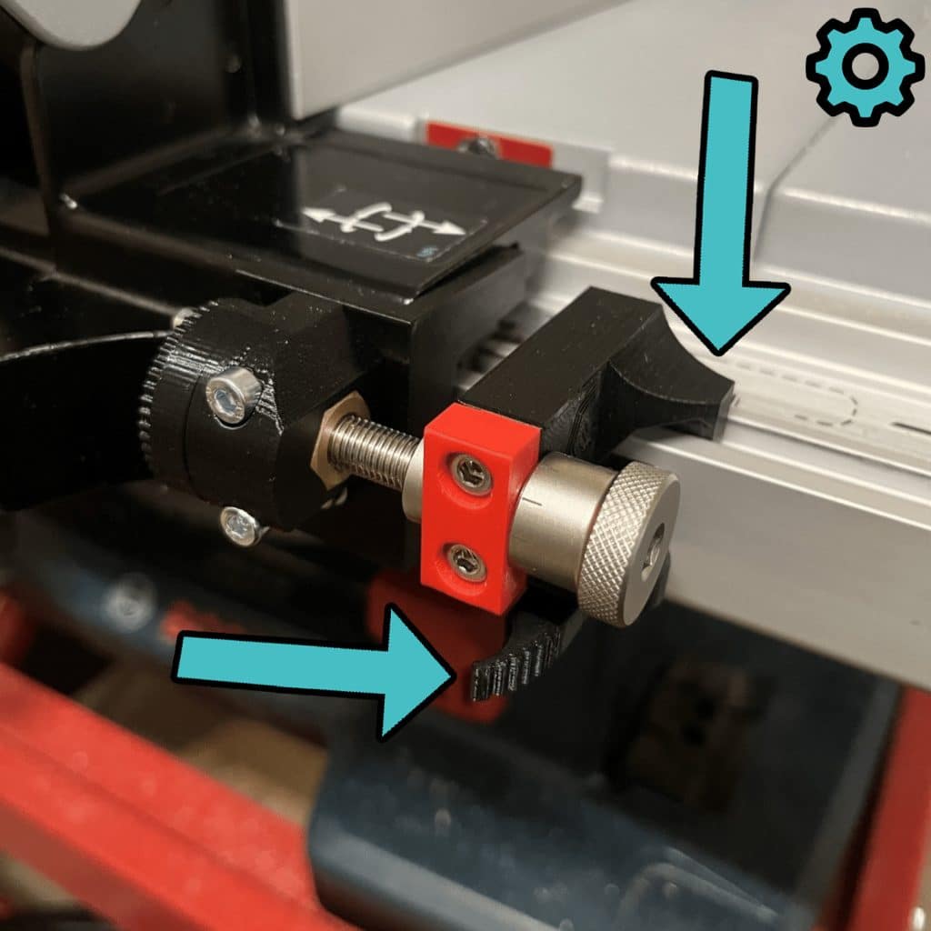
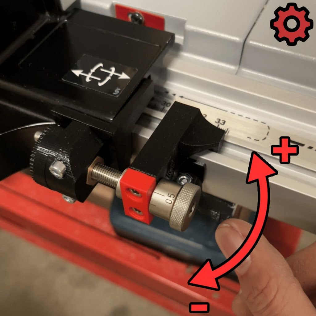
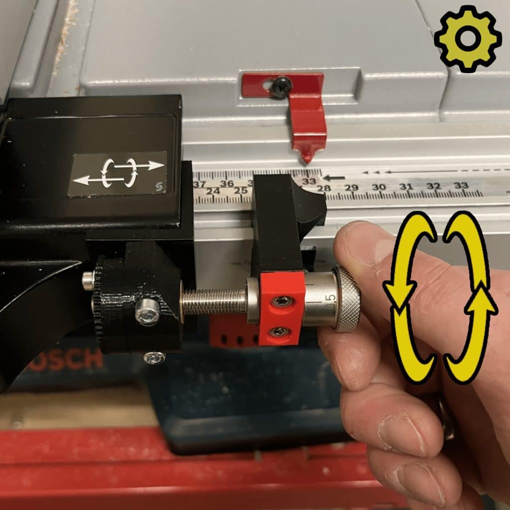
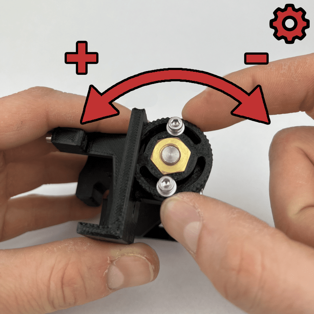
Optimize your woodwork with the GTS 10 xc fine adjustment for the rip fence. Precise adjustment of up to 0,1mm for maximum accuracy and control. Discover the optimization for the GTS 10 xc and reach the next level in your work!


Slightly

Allen key 2,5mm
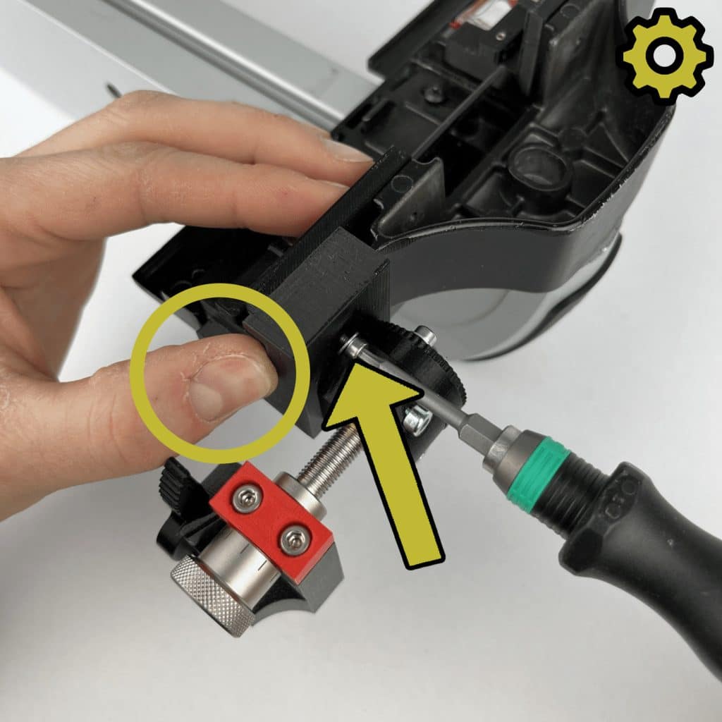
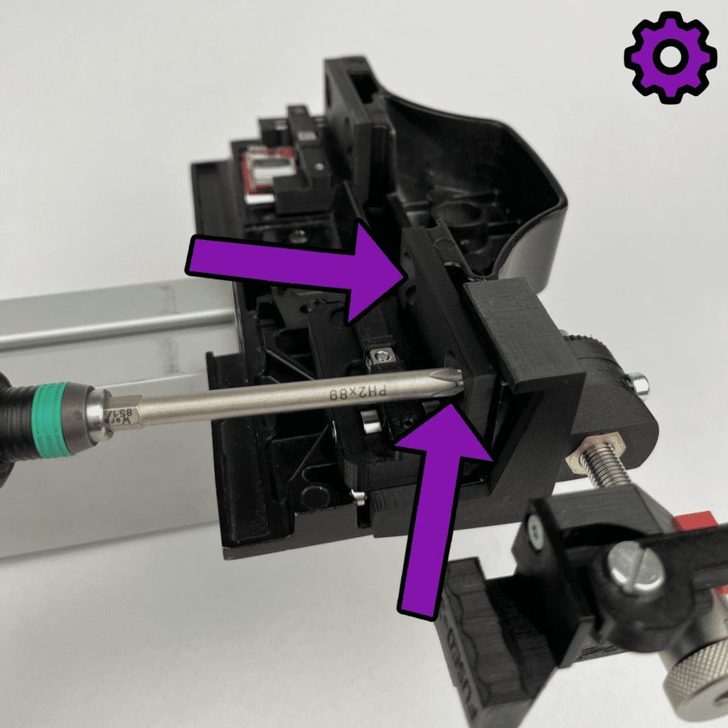
Phillips screwdriver PH2
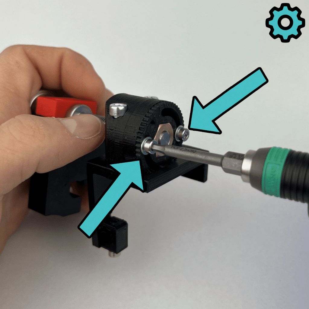
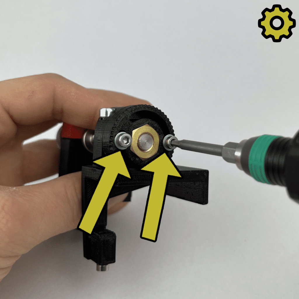


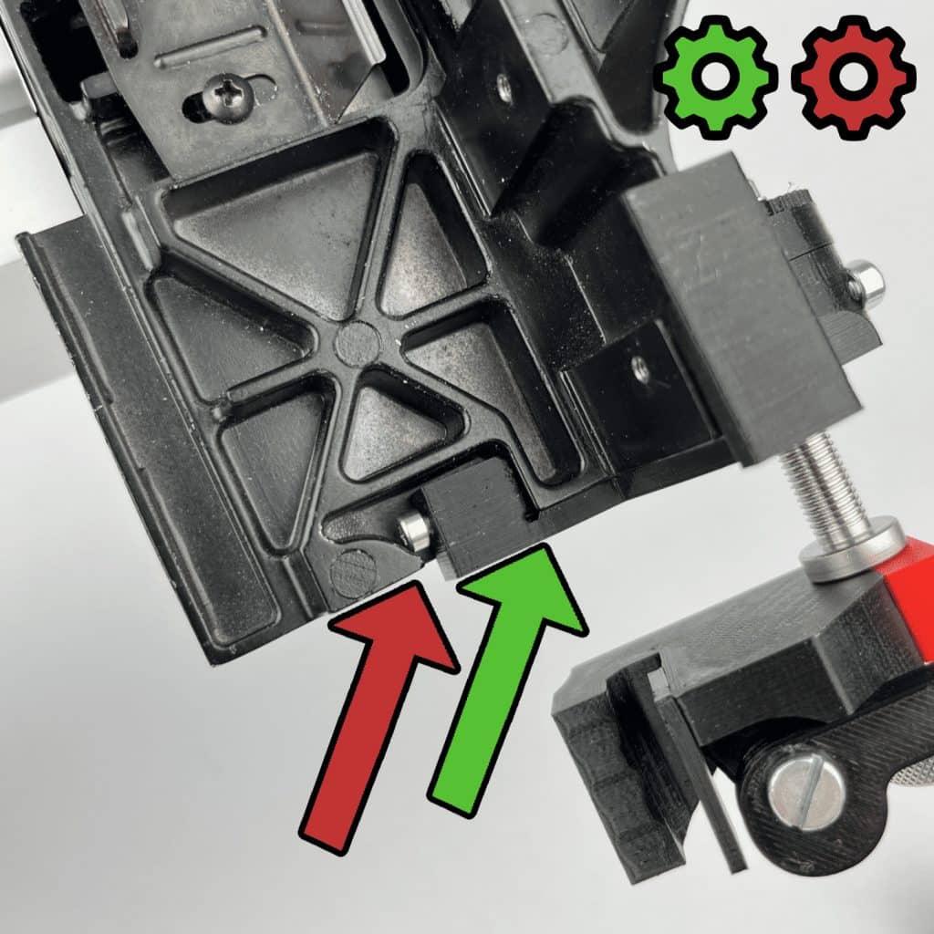
*The play between the brass nuts and the adjusting screw can be changed at any time when the rip fence is installed.


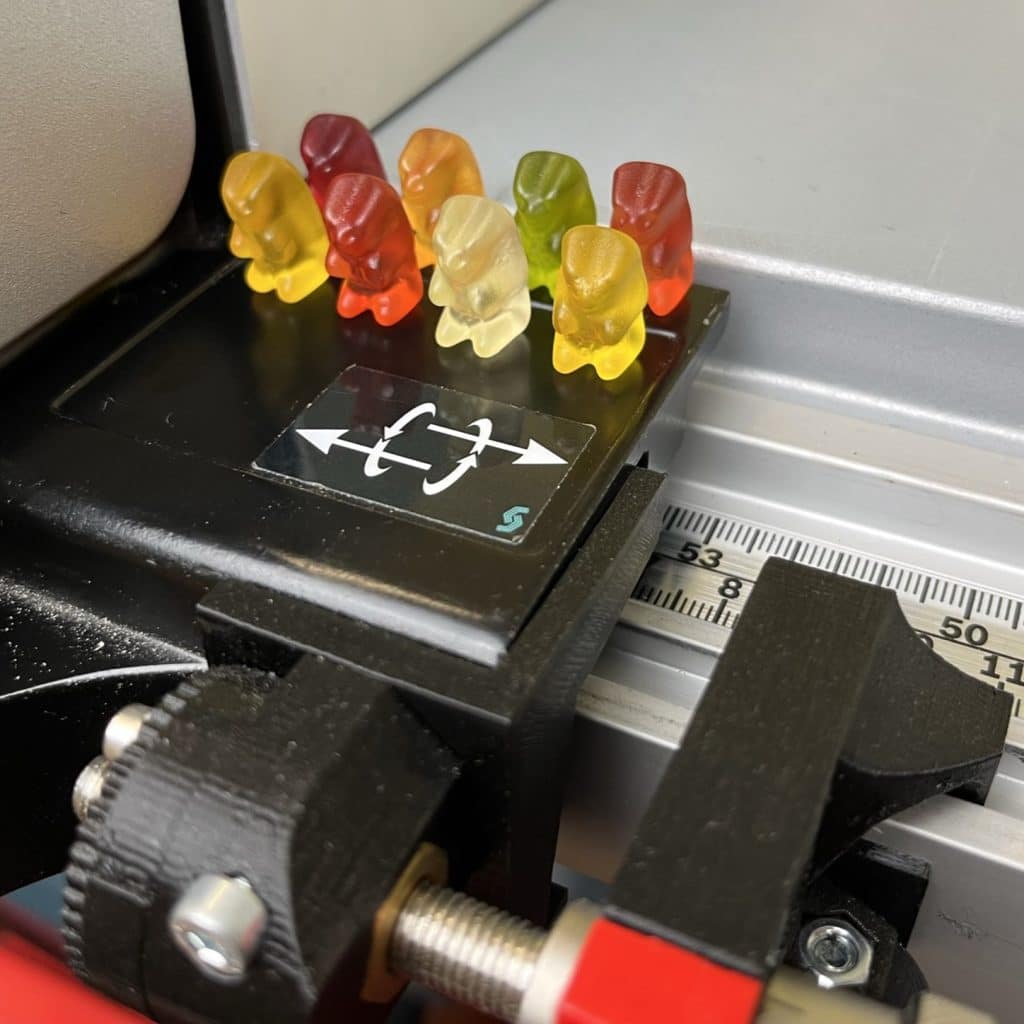
Great, you made it! Gummy bears are waiting for you as a reward. Enjoy your meal!